
Prologue
A Heat Conduction Isothermal Calorimeter is used to determine the heat flow rate of a specific process or reaction, in my case, it is designed to measure the heat rate of hydration of cement in the field of Civil Engineering and Materials Science.
The purpose of this custom-built Isothermal Calorimeter is to undertake the ASTM C1702 Standard Test Method for Measurement of Heat of Hydration of Hydraulic Cementitious Materials Using Isothermal Conduction Calorimetry.
ASTM International, formerly known as American Society for Testing and Materials, is an international standards organization that develops and publishes voluntary consensus technical standards for a wide range of materials, products, systems, and services.
This method is suitable for determining the total heat of hydration of hydraulic cement at constant temperature at ages up to 7 days to confirm specification compliance.
The design is based on the original paper by Dr Lars Wadsö and Xie Li from Lund University in Sweden which was published in the Journal of Chemical Education in 2008 — check the references at the end of this page for more details.
I built this device for educational experimentation and student use in the Materials Science / Structural Engineering Lab (used by a PhD student for her lab experiments) at the Faculty of Engineering, Alexandria University, Egypt. The PhD thesis is titled:
“Modeling of Heat of Evolution and Transfer in Cement Based Materials”
I published the content of this article on HackADay.io in March 2015.
The main goal of this article would be to document the design and build process of this Heat Conduction Isothermal Calorimeter from a scientific paper into an actual device that was used to measure real-life data. May 7, 2015, I received results from the first mixture from the PhD student.
Bill of Materials (BOM)
| Quantity | Item | Description |
|---|---|---|
| 1 | [Teensy 2.0] | ATMEGA32U4 USB board |
| 1 | [MCP3424] | Analog to Digital Converter (ADC) IC |
| 1 | [DS1307 RTC] | Real-Time Clock |
| 1 | [Micro SD card adapter] | Connects directly with the Teensy 2.0 |
| 2 | [HT1-12710] | 40x40x3.3mm Thermopile – Peltier Plate |
| 2 | [Aluminium Vial Holder] | Machined from aluminium cylinder |
| 2 | [Glass Vial] | 30x60mm glass ampoule |
| 1 | [Heat Sink] | 100x50x50mm raw aluminium block |
| 1 | [Outter Enclosure (MDF)] | 25mm MDF Box (300 x 220 x 250mm) Assembled using pocket screws |
| 1 | [Inner Enclosure (Aluminium)] | 3mm aluminium box (200 x 120 x 150mm) |
| 1 | [PU Foam Spray] | PolyUrethane Foam sprayed between the outter and inner enclosure |
| 1 | [3.7V Battery] | Lithium Polymer (LiPo) 4000mAh Rechargeable Battery |
At the time of building this Isothermal Calorimeter, the total cost of the materials was EGP 1370.
Bits and Pieces

An aluminium square block of 50x50mm cross-section sourced from a local supplier and cut into a length of 100mm.

Glass vials or ampoules with 30mm diameter and height of 60mm bought from a local chemistry lab shop and came with a glass lid.

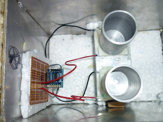
An aluminium vial holders were machined from an aluminium cylinder using a lathe at a local metal shop. I provided the exact dimensions to the shop, and they machined it with excellent precision. You can see above the glass vial fitting nicely inside one of the aluminium vial holders.

The thermopiles or Peltier plates fitted on top of the aluminium heat sink using thermal paste and then secured using blobs of 8-minute epoxy around the corner to provide extra security. The thermopiles were sourced from eBay. This thermopile plate has 127 thermocouples each and a temperature rating of up to 200°C.
The Build
Calibrating the Calorimeter
It’s time for calibrating the calorimeter! There are two parameters I’m interested in for the cement hydration process, which are:
- The Calibration Coefficient
- The Baseline
The Calibration Process
Measuring The Calibration Coefficient
I used the following items:
- A pair of 1/4W and 0.1% accuracy 120Ω precision resistors, they will act as the heaters during the calibration process. One is placed inside the sample vial, and the other is an external resistor placed in series with the one inside the vial to be able to measure the current going through the resistor (to eliminate errors from resistor leads).
- An external power supply to go through the resistors is a 12V DC coming from an ATX computer power supply or a 9V DC battery.
- And, a multimeter to measure the voltage across the external resistor.
The schematic of the calibration circuit (referenced from the paper):

The Procedure

I put one of the resistors inside the sample vial and secured it with tape (a more reliable method is to use glue or paraffin oil as suggested in the original paper for thermal conductivity). This resistor would be (Rh).
Afterwards, I connected the external battery with the external resister as well as the resistor inside the sample vial all in a series connection. Then connect the multimeter over the external resistor. Don’t switch on the external battery yet!
Switch on the calorimeter circuit which will start recording data to the SD card, and if you are using the serial monitor on Arduino IDE you will see the data in real-time as well.
Now record the initial baseline reading (U1) as soon as the signal is stable.
Turn on the external battery now, which will produce heat as it goes through the resistor. Write down the voltage over the external resistor using the multimeter (Ux).
Leave the external battery ON until a stable signal is reached again, this will be our (U2).
Now disconnect the external battery.
Leave the calorimeter data logger recording until we reach a final reading baseline (U3).
Stop the calorimeter data logger.
Now the current through the resistor is

The thermal power produced in the resistor is

The output signal is

Finally, the calibration coefficient is

This is a photo of my setup during the calibration process, where the glass vial with the resistor is inserted into the calorimeter and sealed with a piece of foam, the internal body of the calorimeter is insulated from outside using the MDF wood layer, an inner layer of PU foam separating the MDF layer and most inner layer of aluminium.

Obtaining The Baseline
The original paper suggests doing a baseline calibration even if it was recorded during the calibration coefficient procedure, by doing so we eliminate any baseline drifts caused by a non-perfect balance between reference and sample vials. So we charge both vials with inert sample (in my case, Sand) and we measure a reading over a week or something.
Calibration Results
The calibration coefficient and the baseline were calculated using the calibration procedure explained in the prior section.

Next, I calculated the heat of hydration of a cement sample using the set of equations below and with some help from the PhD student.


Where,
U: Calorimeter Output in Volts (V)
P: Thermal Power in Watts (W)
Q: Heat Produced in Joules (J) or J/g
mc: Cement Weight in grams (g)
The duration of the experiment was initially planned to be three days.
Also, the calorimeter readings were logged every 5 seconds onto the microSD card.
The First Prototype
I started working on the actual prototype on January 22, 2015.
More photos from the build,


After finishing the prototype, I calibrated my sensors by adding water in the reference vial, so this calibration coefficient will work with a solution but I will have to re-calibrate it for cement.
The calibration for cement will require filling the reference (inert) vial with Sand or NaCl (Sodium Chloride) because the specific heat capacity for water is 4182 J/kg while Concrete is 880 J/kg which matches that of Salt and NaCl of 880 J/kg. Sand will be accessible in our Lab, and its specific heat capacity is 830 J/kg.
The PhD student at my faculty used this device to perform the heat of hydration of cement experiment for seven days as instructed by the ASTM C1702. The data was logged to the micro SD card into a CSV file format in 5-second intervals/readings (which could be opened via LibreOffice Calc or any spreadsheet processing program).
Actual Readings
I added some NaHCO3 with water (exothermic reaction) into the sample vial, and the reference vial contained Sand at that time.
The following is a plot of the raw calorimeter readings in micro-Volts versus the time in seconds; the plot was created in Python using matplotlib. Click plot for full size image.

I thought I should add the thermal power after conversion as well in milli-Watts, click plot for full size image

Thesis Acknowledgement
I was delighted to be acknowledged by the PhD student in her thesis, and I am very proud of building something that could help the academic community.
Below you can find some pages from the thesis which are publicly available from the Alexandria University Academic Library Database website — please note that they will open in this same page,
The first page / cover page of the thesis with the title
The acknowledgment page with mine in the third paragraph
More Details
If you find this post missing any critical details, information, instructions or any other insights, please don’t hesitate to ask and I will be happy to update it and share it with you. I could have added more details to this post, but it would have delayed the publishing of the post itself, IMHO: I think it would be better to publish it with the community and then update it on a request-by-request basis.
References
ASTM C1702-17, Standard Test Method for Measurement of Heat of Hydration of Hydraulic Cementitious Materials Using Isothermal Conduction Calorimetry, ASTM International, West Conshohocken, PA, 2017, www.astm.org
Wadsö, L. and Li, X., 2008. A simple rate law experiment using a custom-built isothermal heat conduction calorimeter. Journal of Chemical Education, 85(1), p.112.